Baseboard Joints
Tom Cunnington
19th May 2015
5 minutes
Baseboard joints are a necessary evil if you ever have to move your layout. Scenically they create what is often an obvious rift line across our otherwise beautiful handiwork, but operationally they can be a major cause of unreliability. So I try to make the joints as unobvious as I can, but robust enough to stand the knocks and bangs that happen to all portable layouts and maximise the chances of good operation.
It is very difficult to make a board joint better later – so I spend time getting the basics right.
This starts with good baseboard construction with wood that shouldn’t move as it dries, and good alignment dowels to get the rail positions consistently right. The cheap dowels tends to have too much movement for my liking; there should be a good snug fit between the halves. I’m less worried about the clamping bolts – they need to work, but they shouldn’t be the mechanism for alignment.
The baseboard surfaces need to be level – or at least avoid any change in gradient around the joint so your stock doesn’t have extra changes in direction to cope with where there is a gap in the rail. I personally don’t like foam or even cork underlay – I like to build rack onto a firm base so it stays firm – I know this is unprototypical but this way works for me.
Having got the foundations right, the critical issue for me is to fix the rail ends solidly in place, normally by soldering the rail to something larger and easier to fix to the wood. There are a variety of methods, several of which I’ve tried. I don’t like using copperclad paxolin – it is more difficult to solder rail to due to the copper acting as a heat sink, and on some types the copper actually delaminates from the substrate if you get it too hot; It is difficult to hide scenically (although I have seen some good attempts, and perhaps not noticed the really good versions).

C&L Finescale make what they call end protectors, which are brass etches that get countersunk in the baseboard ends. I used these on a previous layout with some success, but they don’t work as well where rails are converging as the lollipop bits have to be cut back. You can see where I started to use them on Minories before moving onto my preferred method. The C&L is on the left.

I now use large round head brass screws, No. 8, 1.5 to 2” long, screwed into the wood and onto which it is easy to solder the rail to. Once I know the position of the track, I drilled pilot holes so that the edge of the screws were very slightly (0.5mm) over the edge of the board joint. But far enough in that the thread wasn’t going to come through the wood below, The screws were screwed in, with a very small amount of glue to stop any movement, with the flat bottom surface of the heads firmly against the wood, but not so tight to damage the wood. I filed the edges off the screws so they were flush with the end of the board.

Then with a section of track, I pulled the sleepers back to there was a section of rail the about 1” long to use as a height gauge for the top of the screws. I filed the tops of the screws down so that the track just slid over them with just enough room for a small amount of solder.

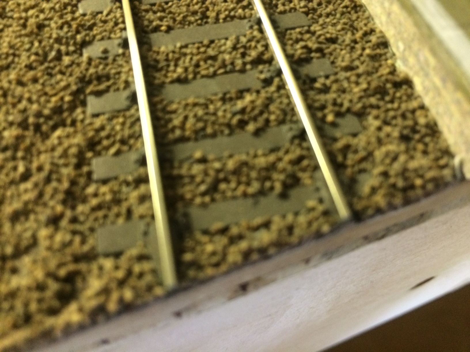
Then I used an small saw (but a file would do) to cut the sides off the screw, at a slight angle, so that the top of the screw was the same width as the bottom web of the rail, but about 6mm in length under the rail going back from the board edge – see the right hand screw below (the left hand one has been filed flat)

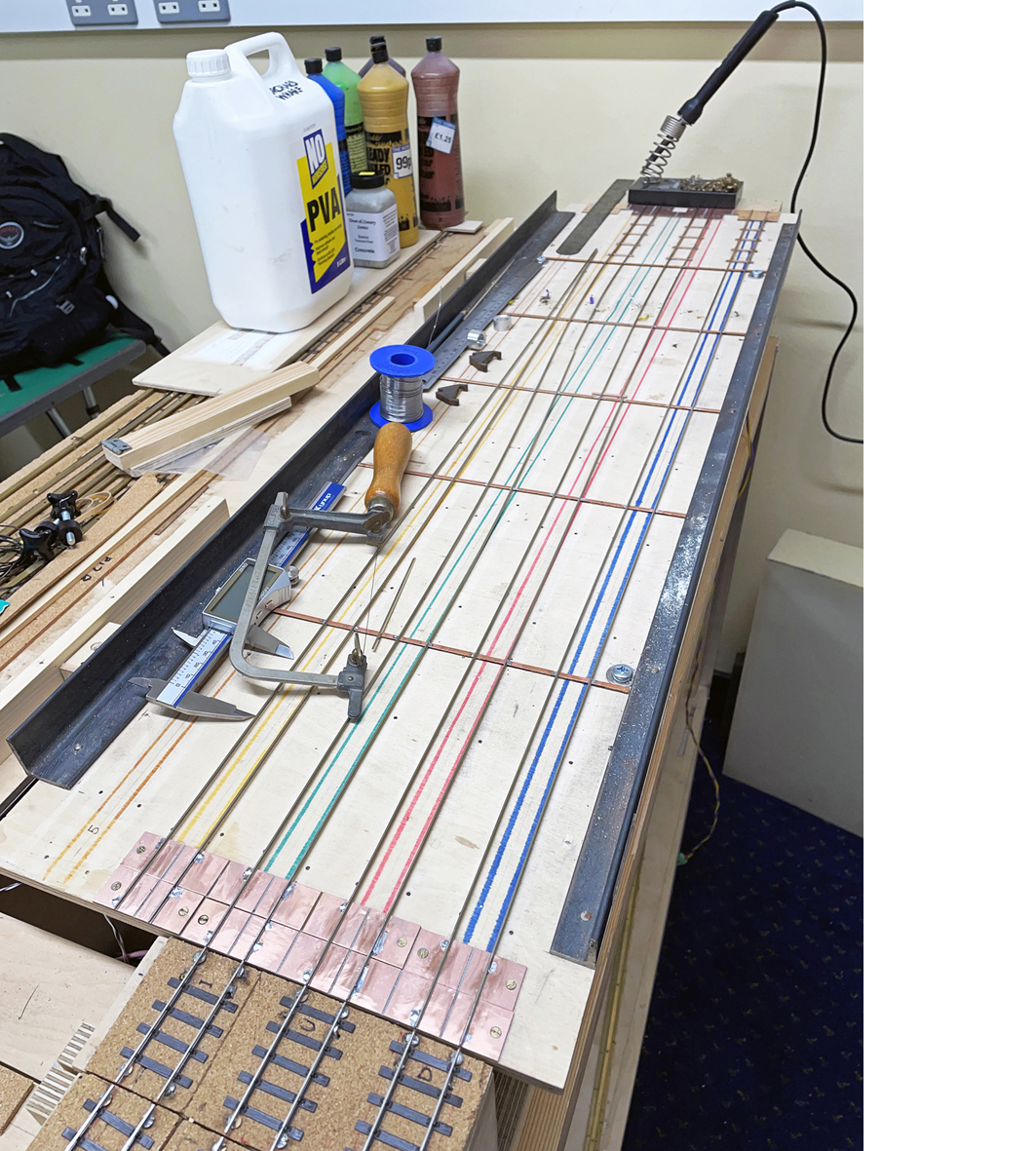
These picture show a piece of track to check it lines up, and the tools used for this stage


The actual track to be laid is then prepared, but with the sleepers cut back / off around the joint maintaining the spacing on either side as it would be if it was a plain piece of rack. Give the bottom of the rail a clean whilst you can. Try to lay the track so that there wouldn’t be a sleeper across the joint itself. I try to lay track in warm / hot conditions so the rail is expanded. I’ve never had a real problem with rail contracting and opening up expansion joints; I have had awful problems with rails expanding as exhibitions get surprisingly warm.
The track is fixed down using your preferred method on either side of the joint (mine is initially superglue to tack every 4th sleeper in place, followed by PVA with the ballast for final fixing – with nails I hit and damage the rail every so often, so avoid the risk). Then using plenty of flux when I solder the rails, one at a time, to the flattened screw tops. I prefer a very hot iron with fairly high melt solder (221) so I can get in and out quickly but get a good firm joint. If you take longer, there is a risk that the heat will travel back along the rail and melt the plastic sleepers. Let the rail cool between each solder joint, and at the clean off any flux with some water to avoid future corrosion. Check the track and soldering looks good from all angles (it’s much easier to change things before you cut the rails) and make sure some stock runs over it smoothly. Then carefully so as not to damage the track on either side use a razor saw to cut through each rail at a time.
The final stage is to take the sleepers you cut off the rail, and cut them to fit around the screw heads and glue them in place to make it look as though the sleepers are continuous across the joint.

In fiddle yards etc you don’t have to bother with making the screws heads look pretty. I still prefer to use a round head with a filed down top to get the firm seat against the wood, but I have used countersunk screws screwed to the right point to make the heads level with the rail bottom, and just soldered the rail in place.
If you’ve found this useful, why not check out other blogs – including building track, converting models to EM Gauge or about our layouts including Minories
And find out about the benefits of joining us
You may also like...
Thursday Track Nights
We are open on Thursday evenings from 7pm to 9pm at our Keen House clubrooms. Visitors are welcome, please come along and introduce yourself.
Address:
Keen House, 4 Calshot Street, London, N1 9DA
Become a member